
Product Description
Product Description
1 Twin Tapered Output Hub
A tapered bore in both sides of the reducer’s output hub snugs up against a matching taper on the outer surface of the bushing. Bushing mounting screws pass through the bushing flange into a mounting collar on the hub. As the screws are tightened, the bushing moves inward, gripping the driven machine’s input shaft tightly and evenly around every pointon its circumference. It is easy-on, easy-off. All the Output Bushing Bore accord to ANSI
2 Precision High Quality Gearing
Computer Design Helical Gears, Strong Alloy Materials for High Load Capacity, Case Carburized for long life, Ground Profile CHINAMFG tooth Profile, In
Conformance with ISO 1328-1997, 98% Efficiency for Per Stage, Smooth Quiet Operation with Several Teeth in Mesh.
3 Maximum Capacity Housing Design
Close Grain Cast Iron Construction, Excellent Vibration Dampening & Shock Resistance Features, Precision Bored and Dowelled to Ensure Accurate In-Line Assembly.
4 Strong Alloy Steel Shafts
Strong Alloy Steel, Hardened, Ground on Journals, Gear Seatings and Extensions, for Maximum Load and Maximum Torsional Loads. Generous Size Shaft Keys for Shock Loading.
5 Use adapter for mount the torque arm, increase the strength of the gear case, the torque armeasy-on and easy-off and reliability, controls position of standard torque arm mounting within recommended limits.
6 BackStops
Alternative Parts, anti-run back device, are available on all 19:1, 15:1 and 25:1 ratio units.
7 Bearings and Oilseals
Bearings are all tapered roll bearings(Except SMRY-2), have long time service time. Oilseals are Double Lipped Garter Spring Type, Ensuring Effective Oil Sealing.
8 Torque Arm Assembly
For Easy Adjustment of the Belt.
| size | Nominal ratio 15:1 | Nominal ratio 25:1 | weight lbs | ||||
| Actual Ratio | Maximum Input rpm | Maximum Ouput rpm | Actual Ratio | Maximum Input rpm | Maximum Ouput rpm | ||
| SMRY-2 | 14.04 | 1974 | 140 | 23.37 | 1994 | 85 | 58 |
| SMRY-3 | 14.87 | 2083 | 140 | 24.75 | 2100 | 85 | 98 |
| SMRY-4 | 15.13 | 2118 | 140 | 24.38 | 2072 | 85 | 139 |
| SMRY-5 | 15.4 | 1925 | 125 | 25.56 | 2044 | 80 | 207 |
| SMRY-6 | 15.34 | 1916 | 125 | 25.14 | 2571 | 80 | 285 |
| SMRY-7 | 15.23 | 1827 | 120 | 24.84 | 1863 | 75 | 462 |
| SMRY-8 | 15.08 | 1809 | 120 | 24.62 | 1847 | 75 | 633 |
| SMRY-9 | 15.12 | 1814 | 120 | 25.66 | 1925 | 75 | 760 |
size SMRY-2, 3,4,5,6,7,8,9 , ratio 15:1 ,25:1
Company Profile
l The largest manufacturer and exporter of worm gear reducers in Asia.
l Established in 1976, we transformed from a county owned factory to private 1 in 1996. HangZhou SINO-DEUTSCH POWER TRANSMISSION EQUIPMENT CO.,LTD is our new name since 2001.
l We are the first manufacturer of reducers and gearboxes in China who was given export license since year 1993.
l “Fixedstar” brand gearboxes and reducers are the first owner of CHINA TOP BRAND and Most Famous Trade Mark for reducers.
First to achieve ISO9001 and CE Certificate among all manufacturers of gearboxes in China.
As a professional manufacturer of worm gearbox and worm gear reducers in China, we mainly produce reduction gearbox,aluminum case worm gearboxes,arc gear cylindrical worm gearboxes, worm gear reducers, in line helical gearboxes, and cyclo drive reducers, etc. These products feature rational structure, stable performance, and reliable quality, and so on. They are widely used in power, mining, metallurgy, building material, chemical, food, printing, ceramic, paper-making, and other industries.
We have 600 workers in our factory, which covers 70,000 square CHINAMFG in HangZhou. We have been making 2,500 units of reducers everyday since 2012. We are proudly exporting 70% of our products to more than 40 countries all over the word. Our customers come from Italy, Germany, USA, Canada, Spain, UK, Mexico, Brazil, Argentina, Turkey, Singapore and other main industrial countries in the world. 30% of them are OEM made for direct manufacturers of other products.
We warmly welcome customers from other parts of the world to visit us. Seeing is believing. We are very confident that after visiting our facility, you will have confidence on our products. We have the latest automatic equipments and experienced workers to ensure the stable quality and large output. We have the most sophisticated technical and engineering team to support most demanding requirement on standard and OEM products.
Looking CHINAMFG to meeting you in HangZhou, China.
/* January 22, 2571 19:08:37 */!function(){function s(e,r){var a,o={};try{e&&e.split(“,”).forEach(function(e,t){e&&(a=e.match(/(.*?):(.*)$/))&&1
| Application: | Machinery, Agricultural Machinery, Industry |
|---|---|
| Function: | Distribution Power, Change Drive Torque, Speed Changing, Speed Reduction |
| Layout: | Parallel |
| Hardness: | Hardened Tooth Surface |
| Installation: | Vertical Type |
| Step: | Single-Step |
| Customization: | Available | Customized Request |
|---|
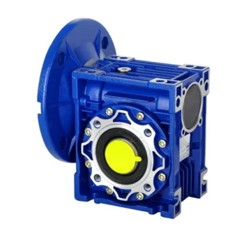
How to Install and Align a Worm Reducer Properly
Proper installation and alignment of a worm reducer are crucial for ensuring optimal performance and longevity. Follow these steps to install and align a worm reducer:
- Preparation: Gather all the necessary tools, equipment, and safety gear before starting the installation process.
- Positioning: Place the worm reducer in the desired location, ensuring that it is securely mounted to a stable surface. Use appropriate fasteners and mounting brackets as needed.
- Shaft Alignment: Check the alignment of the input and output shafts. Use precision measurement tools to ensure that the shafts are parallel and in line with each other.
- Base Plate Alignment: Align the base plate of the reducer with the foundation or mounting surface. Ensure that the base plate is level and properly aligned before securing it in place.
- Bolt Tightening: Gradually and evenly tighten the mounting bolts to the manufacturer’s specifications. This helps ensure proper contact between the reducer and the mounting surface.
- Check for Clearance: Verify that there is enough clearance for any rotating components or parts that may move during operation. Avoid any interference that could cause damage or performance issues.
- Lubrication: Apply the recommended lubricant to the worm reducer according to the manufacturer’s guidelines. Proper lubrication is essential for smooth operation and reducing friction.
- Alignment Testing: After installation, run the worm reducer briefly without a load to check for any unusual noises, vibrations, or misalignment issues.
- Load Testing: Gradually introduce the intended load to the worm reducer and monitor its performance. Ensure that the reducer operates smoothly and efficiently under the load conditions.
It’s important to refer to the manufacturer’s installation guidelines and specifications for your specific worm reducer model. Proper installation and alignment will contribute to the gearbox’s reliability, efficiency, and overall functionality.
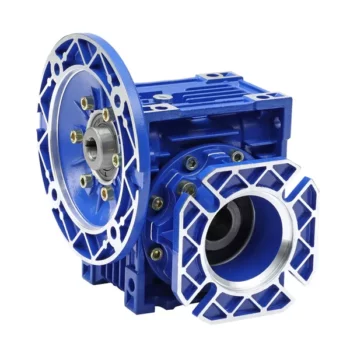
How to Calculate the Input and Output Speeds of a Worm Gearbox?
Calculating the input and output speeds of a worm gearbox involves understanding the gear ratio and the principles of gear reduction. Here’s how you can calculate these speeds:
- Input Speed: The input speed (N1) is the speed of the driving gear, which is the worm gear in this case. It is usually provided by the manufacturer or can be measured directly.
- Output Speed: The output speed (N2) is the speed of the driven gear, which is the worm wheel. To calculate the output speed, use the formula:
N2 = N1 / (Z1 * i)
Where:
N2 = Output speed (rpm)
N1 = Input speed (rpm)
Z1 = Number of teeth on the worm gear
i = Gear ratio (ratio of the number of teeth on the worm gear to the number of threads on the worm)
It’s important to note that worm gearboxes are designed for gear reduction, which means that the output speed is lower than the input speed. Additionally, the efficiency of the gearbox, friction, and other factors can affect the actual output speed. Calculating the input and output speeds is crucial for understanding the performance and capabilities of the worm gearbox in a specific application.

Preventing Backlash in a Worm Gearbox
Backlash in a worm gearbox can lead to reduced accuracy, positioning errors, and decreased overall efficiency. Here are steps to prevent or minimize backlash:
- High-Quality Components: Use high-quality worm gears and worm wheels with tight manufacturing tolerances. Precision components will help reduce backlash.
- Proper Meshing: Ensure the worm gear and worm wheel are properly aligned and meshed. Improper meshing can lead to increased backlash.
- Preload: Applying a small amount of preload to the worm gear can help reduce backlash. However, excessive preload can increase friction and wear.
- Anti-Backlash Mechanisms: Consider using anti-backlash mechanisms, such as spring-loaded systems or adjustable shims, to compensate for any inherent backlash.
- Lubrication: Proper lubrication can reduce friction and play a role in minimizing backlash. Use a lubricant that provides good film strength and reduces wear.
- Maintenance: Regularly inspect and maintain the gearbox to identify and address any changes in backlash over time.
It’s important to strike a balance between reducing backlash and maintaining smooth operation. Consulting with gearbox experts and following manufacturer guidelines will help you optimize your worm gearbox’s performance while minimizing backlash.


editor by CX 2024-03-28